After seeing several Timelapses with movement in them I decided it was time to build myself a Dolly to give my shots some movement. After doing a few googles I found a few images of a simple but easy to build setup on flickr (link)
This was enough to give me an idea of what the dolly build should be like, however i still wasn’t sure how i should control the dolly and stepper motor or drive the dolly, or even if I had the skills. I have previously played with arduino but really only got as far as led light flashing;
and a little project for an intervalometer for my Sony Nex camera (see my previous post)
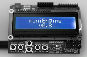
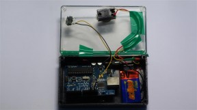 I was fairly lost at how to ramp up to a motorised dolly system, thankfully core-moran over at openmoco (The Open Source Photographic Motion-Controll Community) has been working on a ripper sketch/application called MiniE (Mini Engine). This is basically a Arduino sketch to control a camera and single stepper motor for movement.
So At this point i realise i should be capable to get a motor working, but i wasnt sure how i would make the dolly move from the motor. My first thought was a worm drive system like you see in the cnc system like:
However worm drives are mega expensive ($200+) so i ventured to bunnings and found a threaded rod. This is the first prototype of the system to ensure that my idea does work:
Confirmed that my theory will work i decided it was time to grab some bits and pieces;
Stepper motor:
 This is a SparkFun ROB-09238 Stepper motor (link) I got it from protogear in Australia.
I also got a driverboard to drive the motor:
 This is another SparkFun part the Easy Driver (link) again i got it from ProtoGear (link) here in Australia. You could in theory build your own stepper motor driver but personalyl I found this much easier.
I also needed a protoboard, a place to put all my components.
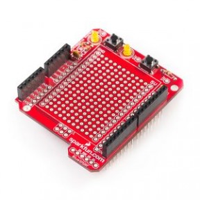 Another Sparkfun item the ProtoshieldKit Links: (Sparkfun) (Protogear AU), Keep in mind here that to put it together you need to solder it. Dont be scared tho, if i can do it so can you.
I also grabbed 2 items off ebay each below $20;
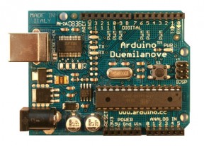
A new Arduino Duemilanove;
I wanted to grab this for two reasons, firstly i wanted to continue using my other Arduino and the LCD shield (below) said it needed a Duemilanove or newer).
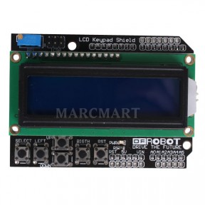
DFrobot (or chinese clone) LCD display and keypad.
This is what the Openmoco MiniE needs for interaction, and at $20 for the setup its a great deal.
In addition to these items i have a 12Volt battery (9Amp hour) to power the motor and a cheapish (~20 bux {I regret this now its well worth getting a decent one}) soldering iron, wire , solder etc.
When the parts started to arrive my first fear was realised, soldering tiny parts with a big cheap soldering iron. Normally you would use something called a set of helping hands:
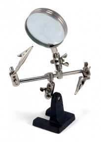 However as per normal no one in Adelaide Australia had any :(. So i had to construct my own crazy setup to try and hold the items when i was soldering:
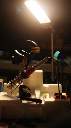 I finished soldering it, as expected it wasnt perfect but it had nice clean joints and worked when testing (tested and soldered following this tutorial): ATTN read below before following tutorial
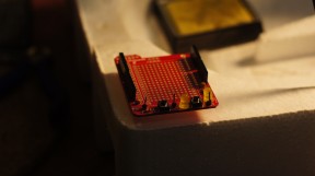
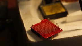
ATTN: After test mounting this board later with the easy driver i found the buttons and test point in the way and had to remove them, so if your soldering honestly all i would solder is the row of pins either side. e.g:
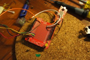 Also another reason not to buy and use a cheap soldering iron, after only about 1hrs of use it started melting and getting really hot.
 So after successfully soldering the protoshield it was time to give controlling the stepper motor a go. It is wired/connected up as per the awesome Buildr Tutorial (link). This is what you (hopefully) end up with:
From here I altered the above tutorials code so it would continue to run in a single direction and test it with my sudo worm drive system, this is the real prototype of the setup. All of a sudden i realised that I had no way to couple the stepper motor to the threaded rod. After speaking to Chucky (Santosh) at work he told me about a way to not only couple the drive shaft to the rod, using a piece of pipe and some hose clamps. He informed me of the additional benefit of not requiring the threaded rod to be exactly center due to the flex in the pipe, this also stops the motor bearings from wearing out. Here is a video of the prototype in action:
This is the end of Part 1, I thought this is long enough, in the coming days i will upload the next part showing the dolly coming together. Hopefully this helps you get an idea of what is involved and will let you know where to start.
5 Nov ’11 at 7:34 am
Excellent post!
Great to see another aussie taking the same approach as I’ve been thinking of.
How did you go locating the electronics to build the miniE?
5 Nov ’11 at 6:56 pm
Electronics are real easy to get as there are Australian suppliers for most parts, (I think there are links in the post to an Australian company Protogear where you can get the motor and motor driver) I will endeavor to finish my Part2 of this saga tonight and you can see it in its current shape, but I did work with the MiniE developer and got some professionally printed PCB’s for thismade (Just waiting on them in the mail), and the source for the pcb’s are now included in the miniE project/download. But my next post will show my ghetto setup that has been working fine.