I recently purchased a Arduino DeadOn RTC DS3234 breakout board. (http://www.sparkfun.com/products/10160). Initially i was planning to use this as a (more accurate) replacement for a DS1307, only to find out that the DS1307 uses I2C whilst the DS3234 uses SPI. This blog post is written to hopefully help others avoid wasting an hour or so learning about this chip and how to get it working quickly and easily with an Arduino Diecimila/Duemilanove/Uno.
In basic terms the I2C only uses 2 conenctions (Clock, Data) to communicate over the analog input pin 3 and 4 (Arduino help). In contrast the SPI uses 4 connections to communicate (SS – pin 10, MOSI – pin 11, MISO – pin12, and SCK – Pin13). (Read more at Arduino help).
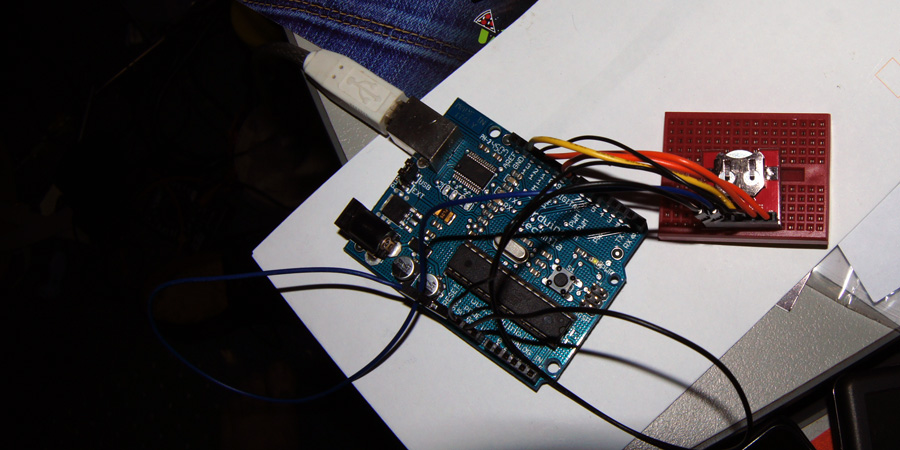
Now we have a short introduction done lets get to the wiring image and getting the sample code (from sparkfun) to run;

You may notice that SS isn’t connected to 10 as SPI documentation stated, this is because sparkfuns example defines pin 8 as part of the sample, you may also notice that there is an additional pin SQW connected to GND, This is to allow the use of the RTC Libary that we will cover later on in the post. First here is the first code snippet of the sparkfun example:
#include <SPI.h>
const int  cs=8; //chip select

void setup() {
  Serial.begin(9600);
  RTC_init();
  //day(1-31), month(1-12), year(0-99), hour(0-23), minute(0-59), second(0-59)
  SetTimeDate(11,12,13,14,15,16);
}

void loop() {
  Serial.println(ReadTimeDate());
  delay(1000);
}
//=====================================
int RTC_init(){
	  pinMode(cs,OUTPUT); // chip select
	  // start the SPI library:
	  SPI.begin();
	  SPI.setBitOrder(MSBFIRST);
	  SPI.setDataMode(SPI_MODE1); // both mode 1 & 3 should work
	  //set control register
	  digitalWrite(cs, LOW);
	  SPI.transfer(0x8E);
	  SPI.transfer(0x60); //60= disable Osciallator and Battery SQ wave @1hz, temp compensation, Alarms disabled
	  digitalWrite(cs, HIGH);
	  delay(10);
}
//=====================================
int SetTimeDate(int d, int mo, int y, int h, int mi, int s){
	int TimeDate [7]={s,mi,h,0,d,mo,y};
	for(int i=0; i<=6;i++){
		if(i==3)
			i++;
		int b= TimeDate[i]/10;
		int a= TimeDate[i]-b*10;
		if(i==2){
			if (b==2)
				b=B00000010;
			else if (b==1)
				b=B00000001;
		}
		TimeDate[i]= a+(b<<4);

		digitalWrite(cs, LOW);
		SPI.transfer(i+0x80);
		SPI.transfer(TimeDate[i]);
		digitalWrite(cs, HIGH);
  }
}
//=====================================
String ReadTimeDate(){
	String temp;
	int TimeDate [7]; //second,minute,hour,null,day,month,year
	for(int i=0; i<=6;i++){
		if(i==3)
			i++;
		digitalWrite(cs, LOW);
		SPI.transfer(i+0x00);
		unsigned int n = SPI.transfer(0x00);
		digitalWrite(cs, HIGH);
		int a=n & B00001111;
		if(i==2){
			int b=(n & B00110000)>>4; //24 hour mode
			if(b==B00000010)
				b=20;
			else if(b==B00000001)
				b=10;
			TimeDate[i]=a+b;
		}
		else if(i==4){
			int b=(n & B00110000)>>4;
			TimeDate[i]=a+b*10;
		}
		else if(i==5){
			int b=(n & B00010000)>>4;
			TimeDate[i]=a+b*10;
		}
		else if(i==6){
			int b=(n & B11110000)>>4;
			TimeDate[i]=a+b*10;
		}
		else{
			int b=(n & B01110000)>>4;
			TimeDate[i]=a+b*10;
			}
	}
	temp.concat(TimeDate[4]);
	temp.concat("/") ;
	temp.concat(TimeDate[5]);
	temp.concat("/") ;
	temp.concat(TimeDate[6]);
	temp.concat("     ") ;
	temp.concat(TimeDate[2]);
	temp.concat(":") ;
	temp.concat(TimeDate[1]);
	temp.concat(":") ;
	temp.concat(TimeDate[0]);
  return(temp);
}
Once uploaded keep the Arduino program open, and go to Tools -> Serial Monitor, ensure the baud down the bottom right is set to 9600. You should see an output like:

And so on, The code sets the time to 11/12/13 14:15:16 on boot, from there it increments second by second as you would expect. So success, if you have got this far your doing well. But lets get something that would be a little more use to us in our programs.
Thankfully a user (manicbug) made a mod to the standard RTC library (As used with 1307 and chronodots), allowing you to utilise the same code and calls that you may have been using/were using/could use with a DS1307. You can jump onto the github service and download a .zip of the current release or you can use the copy that I’m writing this tutorial with (so it should work) here. Extract the folder inside the zip into your arduino\libraries\ and rename the folder to “ManicbugRTCLib“, If you already have the generic RTClib installed it is best to move it out of the libraries folder(Otherwise it could call the original RTCLIB). Restart the Arduino software. With a new sketch paste in the following code, Alternatively you can go file -> examples -> ManicbugRTCLib -> DS3234.
// Date and time functions using a DS1307 RTC connected via I2C and Wire lib

#include <SPI.h>
#include <Wire.h>
#include <RTClib.h>
#include <RTC_DS3234.h>

// Avoid spurious warnings
#undef PROGMEM
#define PROGMEM __attribute__(( section(".progmem.data") ))
#undef PSTR
#define PSTR(s) (__extension__({static prog_char __c[] PROGMEM = (s); &__c[0];}))

// Create an RTC instance, using the chip select pin it's connected to
RTC_DS3234 RTC(8);

void setup () {
    Serial.begin(57600);
    Serial.println("RTClib/examples/ds3234/");
    SPI.begin();
    RTC.begin();

  if (! RTC.isrunning()) {
    Serial.println("RTC is NOT running!");
    Serial.print("Setting time to... ");
    Serial.print(__DATE__);
    Serial.print(' ');
    Serial.println(__TIME__);
    // following line sets the RTC to the date & time this sketch was compiled
    RTC.adjust(DateTime(__DATE__, __TIME__));
  }
}

void loop () {
    const int len = 32;
    static char buf[len];

    DateTime now = RTC.now();

    Serial.println(now.toString(buf,len));

    Serial.print(" since midnight 1/1/1970 = ");
    Serial.print(now.unixtime());
    Serial.print("s = ");
    Serial.print(now.unixtime() / 86400L);
    Serial.println("d");

    // calculate a date which is 7 days and 30 seconds into the future
    DateTime future (now.unixtime() + 7 * 86400L + 30 );

    Serial.print(" now + 7d + 30s: ");
    Serial.println(future.toString(buf,len));

    Serial.println();
    delay(3000);
}
// vim:cin:ai:sw=4 sts=4 ft=cpp
Once uploaded keep the Arduino program open, and go to Tools -> Serial Monitor, ensure the baud down the bottom right is set to 57600. You should see an output like:

You will notice that the time is now formatted correctly, still as 11/12/13 14:16:17 (+ time since previous program). This is because the RTC has continued to run since your last program, The easiest way to fix this is to unplug the Arduino pop the battery out of the RTC wait 5 seconds then put the battery back in and connect the Arduino and compile& upload the program again (quickly if you want it super accurate). This will set the time to the same time as the sketch was compiled and uploaded, from here it should continue on and keep time. Unfortunately after all this the SPI of the DC3234 uses pins that are already in use, looks like its time to buy or build a chronodot that can utilise the unused analog pins and keep similar accuracy.
I Hope this tutorial helps someone out there, let me know how you go and what you think. I’m no expert with this, but I’m happy to stumble through and help.
2 Jan ’12 at 5:03 am
Hi Marc,
Thanks for posting the demo. I can’t reproduced your results for both sets of code (and your wiring), instead I get:
maniacbug’s example output:
RTClib/examples/ds3234/
RTC is NOT running!
Setting time to… Dec 19 2011 22:07:39
Dec 31 2165 23:60:60
since midnight 1/1/1970 = 1890322364s = 21878d
now + 7d + 30s: Dec 02 2029 17:33:14
since midnight 1/1/1970 = 2313941504s = 26781d
now + 7d + 30s: May 06 2043 17:32:14
Dec 31 2165 23:60:60
since midnight 1/1/1970 = 1890322364s = 21878d
now + 7d + 30s: Dec 02 2029 17:33:14
sparkfun’s output after I set it with SetTimeDate(19,12,11,21,30,00)
0/0/0 0:0:20
0/0/0 0:1:21
0/0/0 0:0:22
0/0/0 0:1:23
0/0/0 0:0:24
0/0/0 0:1:25
0/0/0 0:0:26
0/0/0 0:1:27
0/0/0 0:0:28
0/0/0 0:1:29
0/0/0 0:0:30
0/0/0 0:1:31
0/0/0 0:0:32
0/0/0 0:1:33
A lot of others are reporting similar problems, but I haven’t seen solutions posted. Any suggestions?
6 Jan ’12 at 9:12 pm
Dan,
I would guess that your issue is firstly you need to wire it the same. Secondly this tutorial was written with arduino .22 environment. Since then Arduino as moved to 1.0. This means you need newer libraries that support arduino 1.0 . Do a google and you will find it. If you cant find it let me know and i will find the URL’s
11 Jan ’12 at 2:04 pm
Thanks, but i did grab the 1.0 libraries. Hopefully Arduino is using them and not the old ones.
#if ARDUINO < 100
#include
#else
#include
#endif
11 Jan ’12 at 2:11 pm
I will give it another go tonight with version 1.0 and see if I can get it working.
1 Feb ’12 at 6:50 am
The arduino example will work if you change
SPI.setDataMode(SPI_MODE1);
to
SPI.setDataMode(SPI_MODE3);
I still haven’t figured out making the Manicbug library work however.
3 Mar ’12 at 6:12 am
Just wanted to let you know that it worked perfect according to your instructions when I just tested it. I’m using Arduino Uno and Arduino 1.0 env. I grabbed the latest zip from here https://github.com/maniacbug/RTClib/downloads
Thanks a bunch, was really helful with the wiring and all!
5 Jun ’12 at 6:59 am
I’m having problems detecting the RTC is not running. When I use maniacbug’s example, and using the 022 libraries (I haven’t moved to 1.0 yet) I get the clock always starting at January 1 2000 00:00:37 (37 second delay of compiling and uploading) and never being set to the compilation time. The wiring is as per the diagram above. What might I be doing wrong?
12 May ’14 at 9:30 am
Do you know of any easy way to get this to just count up from zero seconds when it is turned on?
18 May ’14 at 8:47 am
Set it to 0 when the arduino starts (beginning of your arduinio program), and the RTC will start counting.
12 Nov ’14 at 4:33 pm
Thank you very much for the tutorial it is helpful,
So I am using the DeadOn RTC with and arduino Mega, I changed the pin connections according to the link you gave and the first code worked but I am facing problems with the second code.
These are the errors I am getting:
C:\Program Files\Arduino\libraries\maniacbug-RTClib-256b8e9\RTClib.cpp: In constructor ‘DateTime::DateTime(uint16_t, uint8_t, uint8_t, uint8_t, uint8_t, uint8_t)’:
C:\Program Files\Arduino\libraries\maniacbug-RTClib-256b8e9\RTClib.cpp:73: error: ‘min’ cannot be used as a function
C:\Program Files\Arduino\libraries\maniacbug-RTClib-256b8e9\RTClib.cpp:74: error: ‘min’ cannot be used as a function
C:\Program Files\Arduino\libraries\maniacbug-RTClib-256b8e9\RTClib.cpp:75: error: ‘min’ cannot be used as a function
C:\Program Files\Arduino\libraries\maniacbug-RTClib-256b8e9\RTClib.cpp:76: error: ‘min’ cannot be used as a function
C:\Program Files\Arduino\libraries\maniacbug-RTClib-256b8e9\RTClib.cpp:77: error: ‘min’ cannot be used as a function
C:\Program Files\Arduino\libraries\maniacbug-RTClib-256b8e9\RTClib.cpp: In member function ‘char* DateTime::toString(char*, int) const’:
C:\Program Files\Arduino\libraries\maniacbug-RTClib-256b8e9\RTClib.cpp:157: error: ‘snprintf’ was not declared in this scope
C:\Program Files\Arduino\libraries\maniacbug-RTClib-256b8e9\RTClib.cpp: In member function ‘void RTC_Millis::adjust(const DateTime&)’:
C:\Program Files\Arduino\libraries\maniacbug-RTClib-256b8e9\RTClib.cpp:181: error: ‘millis’ was not declared in this scope
C:\Program Files\Arduino\libraries\maniacbug-RTClib-256b8e9\RTClib.cpp: In member function ‘DateTime RTC_Millis::now()’:
C:\Program Files\Arduino\libraries\maniacbug-RTClib-256b8e9\RTClib.cpp:186: error: ‘millis’ was not declared in this scope
Thank you
12 Nov ’14 at 6:58 pm
Did you remove the original RTCLib?